6.4 Configuration
Configuration zone
If it is the first time your system is configured, please follow the first steps:
You are now ready to configure your vehicule detection zone(s).
By reading this paragraph you will be able to:
Select the camera to be configured,
Create a vehicle detection area,
Configure the size, the position, the orientation of the detection area,
Delete a vehicle detection area,
Select different options for a detection area such as sensitivity of detection and triggering of outputs in case of detection.
Step by step for detection area configuration
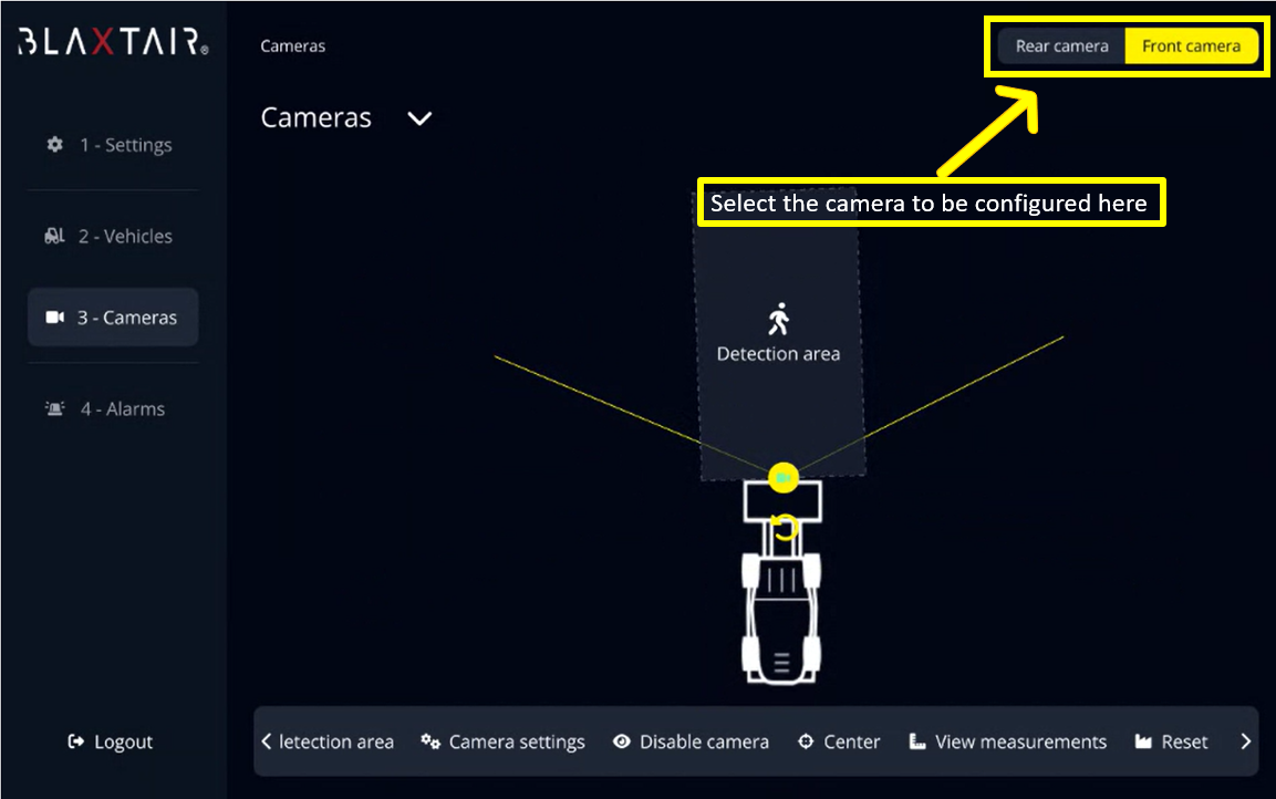
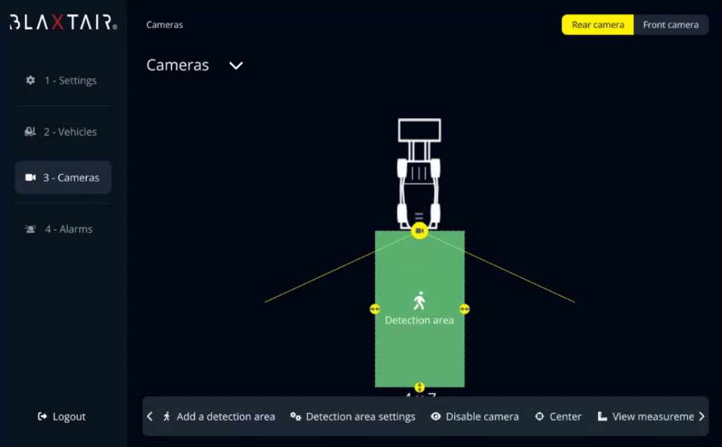
1️⃣ SELECT THE CAMERA TO BE CONFIGURED
Select the camera to be configured by clicking on the buttons at the top right corner:
"Rear camera" corresponds to the camera installed at the rear part of the vehicule
"Front camera" corresponds to the camera installed at the front part of the vehicule
WARNING
A message "Camera disabled" might appear on the screen if the selected camera is not connected to the vehicule or not recognized by the Smart display.
In this case, go back to LIVE MODE and access to [CAMERA SETTINGS] mode to define the FRONT or REAR camera. More details in paragraph [CAMERA SETTINGS].
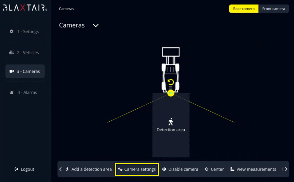
2️⃣ CONFIGURATION OF THE CAMERA SETTINGS
Select the “Camera settings” tab to configure the camera installation parameters
Once you are in the Camera settings:
you need to carefully measure the camera height and camera pitch angle parameters
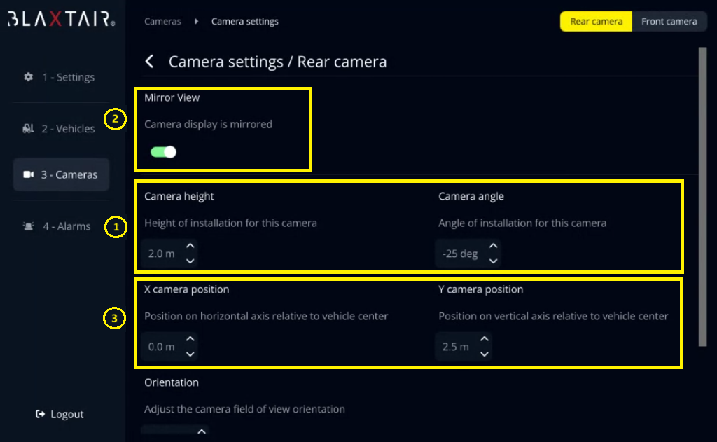
MANDATORY to respect as much as possible the real height and angle to have good performance:
Case A: lower alarm rate than reality
If the camera real pitch angle is higher than the configured pitch angle
the vehicle will be localized more distant than reality
the system could miss some alarms because of the overestimation of localization
Case B: Higher alarm rate than reality
If the camera real pitch angle is lower than the configured pitch angle
the vehicle will be localized closer than reality
the system could raise some alarm for distant vehicle because of the underestimation of localization
you can choose to mirror the camera view → most of the time for rear camera view
you can choose to move the camera position compared to the vehicle center (also feasible manually see below video)
you can choose to move the camera yaw angle compared to the vehicle center (also feasible manually see below video)
Camera field of view is 130°. It is represented by the two yellow straigth lines starting at the camera image on the display.
This parameter is NOT adjustable.
Once this is done and you are sure the camera height and pitch angle are compliant with the installation you can go back to “3-Cameras”
3️⃣ CREATE AND DELETE A DETECTION AREA
The video below explains how to create and delete a detection area
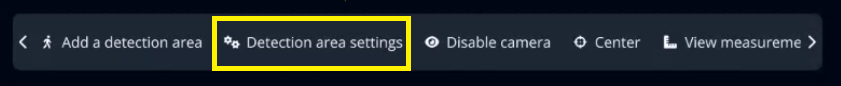
Use the slider menu at the bottom of the screen to create or delete a detection area.
Add a detection area → Click on "Add a detection area"
A detection area appears on the screen. The area is in green. This means that this area is selected and ready for configuration.
Delete detection area
Click on the detection area to be deleted
Click on "Delete detection area"
The selected detection area disappears from the screen.
4️⃣ CONFIGURATION OF THE “VEHICLE” ZONE SETTING
To set a zone in vehicle detection mode, simply click on the zone you wish to configure.
Once the zone is selected the “Detection area” becomes green as illustrated above.
To go on the zone settings you need to click on “Detection area settings”.
You will reach the setting page and be able to settup:
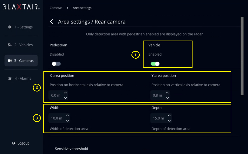
The type(s) of detection you want on the selected zone (only vehicle, only pedestrain or both)
The detection area position relative to the camera (also feasible manually see below “Adjust size and position” video)
The size (width and depth) of the zone (also feasible manually see below “Adjust size and position” video)
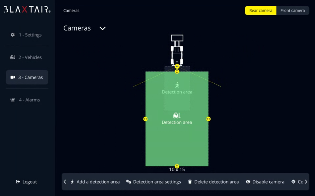
Once this is done and you created a vehicle detection area you can go back to “3-Cameras”. You will have, as illustrated bellow a vehicle “Detection area”.
5️⃣ ADJUST SENSITIVITY AND OUTPUTS
Sensitivity feature allows to adapt the sensitivity of detection to the type of worksite and events. For instance, in a site where the amount of "non pertinent alarms" is high, a medium or low sensitivty could give a better detection rate.
Output feature allows to define which output should be triggered when there is a detection in the selected area. This feature is necessary for installation of an option such as led buzzer, flash beacon or slowdown.
Click on the "detection area settings" button at the bottom menu.
Select desired sensitivity
Low could lead to missed events
High could lead to non pertinent alarms
Activate/deactivate the output triggering using the slider. If feature ON, select the OUTPUT to be triggered depending on your installation. For more details, see 3.6 OUTPUT MANAGEMENT paragraph 5 - Areas.
It is recommanded to keep "Medium" sensitivity as an initial approach.
To save all the changes, click on Save/Quit.