
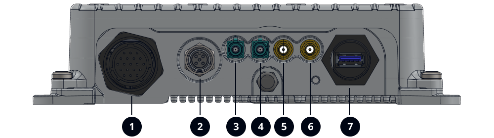
1.2.4' PROCESSING UNIT (pinout)
1 - Pinout
The main connector is connector 1 in the following figure
Processing unit - Main connector - 1 | Main cable connector | ||
|---|---|---|---|
 | 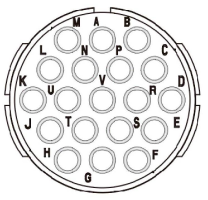 | ||
Pinout | Function | Description | Recommended Wire Gauge |
L | B+ |
Battery Power (+12/+24V) * | AWG20 |
K | B+ |
Battery Power (+12/+24V) * | AWG20 |
N | B- |
Battery Ground * | AWG20 |
U | B- |
Battery Ground * | AWG20 |
M | Ignition | Discrete Input Ignition signal | AWG20 |
B | Disc_In1_GND | Discrete Input 1 Ground | AWG22 |
A | Disc_In1 | Discrete Input 1 Signal | AWG22 |
C | Disc_In2_GND | Discrete Input 2 Ground | AWG22 |
P | Disc_In2 | Discrete Input 2 Signal | AWG22 |
R | Disc_Out1 | Discrete Ouput 1 Signal | AWG22 |
V | Disc_Out1_GND | Discrete Output 1 Ground | AWG22 |
S | Disc_Out2 | Discrete Ouput 2 Signal | AWG22 |
T | Disc_Out2_GND | Discrete Output 2 Ground | AWG22 |
J | Disc_Out3 | Discrete Ouput 3 Signal | AWG22 |
H | Disc_Out3_GND | Discrete Output 3 Ground | AWG22 |
F | CAN_H | CAN - 500kbits on Rload=120R | AWG22 |
G | CAN_L | CAN - 500kbits on Rload=120R | AWG22 |
D | Power_Disc_Out4 | Power Discrete output | AWG20 |
E | Disc_Out4_GND | Power Discrete Ground | AWG20 |
*It is mandatory to connect the two (2) B+ (Pin L & K) on Battery Power and the two (2) B- (Pin N & U) on Battery Ground.
2 - Connector - Part numbers
Connectors
Section | Part number | Description |
|---|---|---|
A-B | UTS71419P | Processing unit Main connector - Souriau connector 19 Pin |
UTS6JC1419S | Main cable - Souriau connector 19 Pin | |
SC20W3S25 | Main cable - 19 x Souriau socket Contact | |
A | Deutsch 3pin | Processing unit power supply |
C | Deutsch 3pin | Power extension |
3 wires | Battery & Ground (12-24VDC) + Engine/Starter (12-24VDC) | |
D | Deutsch 2pin | Display power supply |
E | 8 wires | Discrete Outputs + CAN |
F | 4 wires | Discrete Inpu |